

6369
Methods of Protection in Hazardous (Explosion Risk) Locations: Containment, Segregation and Prevention (with Intrinsic Safety)
07/16/2018
- Explosion containment: The only method that allows the explosion to occur but confines it to a well-defined area, thus avoiding the propagation to the surrounding atmosphere. Explosion-proof enclosures are based on this method.
- Segregation: A method that attempts to physically separate or isolate the electrical parts or hot surfaces from the explosive mixture. This method includes various techniques, such as pressurization, encapsulation, etc.
- Prevention: A method that limits the energy, both electrical and thermal, to safe levels under both normal operation and fault conditions. Intrinsic safety is the most representative technique of this method.
For each method, one or more specific techniques are present that translate into practice the basic philosophy that at least two independent faults must occur in the same place and at the same time in order to ignite an explosion. A fault in a circuit or system that subsequently leads to a failure of another circuit or system is considered a single fault. Naturally, there are limits in considering faults or certain events. For example, the consequences of an earthquake or other catastrophic action may not be considered, because damage caused by the malfunctioning of the protection system during these particular events become insignificant when compared to the damage generated by the main cause.
What, then, are the conditions to be considered?
First of all, the normal functioning of the apparatus must be considered. Secondly, eventual malfunctioning of the apparatus due to faulty components must be a consideration. Lastly, all those conditions that can accidentally occur, such as a short circuit, open circuit, grounding and erroneous wiring of the connecting cables, must be evaluated.
The choice of a specific protection method depends on the degree of safety needed for the type of hazardous location considered in such a way as to have the lowest probable degree of an eventual simultaneous presence of an adequate energy source and a dangerous concentration level of an air/gas mixture.
None of the protection methods can provide absolute certainty of preventing an explosion. Statistically, the probabilities are so low that not even one incident of an explosion has been verified when a standardized protection method has been properly installed and maintained. The first precaution to be used is to avoid placing electrical apparatus in hazardous locations. When designing a plant or factory, this factor needs to be considered. Only when there is no alternative should this application be allowed.
Other secondary, but important, factors for consideration are the size of the apparatus to be protected, the flexibility of the system, the possibility of performing maintenance, the installation cost, etc. Respective of these factors, intrinsic safety has many advantages; however, to better understand these advantages, it is necessary to know and understand the limitations of the other protection methods.
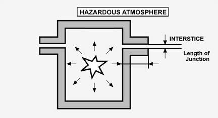
Figure 1. Schematic of an explosion-proof enclosure
EXPLOSION-PROOF ENCLOSURE
This protection method is the only one based on the explosion containment concept. In this case, the energy source is permitted to come in contact with the dangerous air/gas mixture. Consequently, the explosion is allowed to take place, but it must remain confined in an enclosure built to resist the excess pressure created by an internal explosion, thus impeding the propagation to the surrounding atmosphere.
The theory supporting this method is that the resultant gas jet coming from the enclosure is cooled rapidly through the enclosure’s heat conduction and the expansion and dilution of the hot gas in the colder external atmosphere. This is only possible if the enclosure openings or interstices have sufficiently small dimensions (refer to Figure 1).
The purpose of this chapter is to briefly present the different methods of protection. In Europe, CENELEC and IEC standards refer to protection methods with symbols, such as Ex "d" for the explosion proof method. These symbols are not used by the United States and Canada. The principle function of placing symbols on the label of each apparatus is to allow the immediate identification of the protection method in use.
Fundamentally, the required characteristics for an explosion-proof enclosure include a sturdy mechanical construction, contact surfaces between the lid and the main structure, and the dimension of any other opening in the enclosure.
Large openings are not permitted, but small ones are inevitable at the junction points. It is not necessary for the enclosure to be airtight. Sealing the junction is only to increase the degree of protection toward corrosive atmospheric conditions and not to eliminate the interstices. The maximum opening allowed for a particular type of joint depends on the nature of the explosive mixture and width of the adjoining surfaces (joint length).
The enclosure classification is based on the gas grouping and the maximum surface temperature, which must be lower than the ignition temperature of the gas present in the location where they are installed.
The material used to build the explosion-proof enclosure is generally metallic (aluminum, cast iron, welded steel, etc.). Plastic or nonmetallic materials can be used for enclosures with a small internal volume (
In designing an explosion-proof enclosure, the current standards of the country in which the enclosure is to be installed must be consulted. In North America each testing laboratory (e.g., FM, UL, CSA) has its own standard, while in Europe the approval of the authorized laboratory is based on standard EN 50.018.
The North American practice is to test prototypes of the enclosure with a safety margin and not to require additional tests on production models if they conform to the prototype.
The European practice tests the prototype of the enclosure with a much lower safety margin; however, additional tests on the actual production model are required.
Installation and maintenance problems of explosion-proof enclosures
Often, explosion-proof enclosures have installation and maintenance problems that can be summarized as follows:
- A medium-weight enclosure is very heavy, and its installation creates mechanical and structural complications.
- Particularly corrosive atmospheric conditions (characteristic of chemical or petrochemical plants, or oil platforms), require the use of material such as stainless steel or bronze, resulting in dramatically higher costs.
- Cable entries require a particular arrangement (reductions, cable clamps, conduits, metal-clad cable, sealing) and, in some cases, such items may represent a cost higher than the enclosures themselves.
- In a particularly humid atmosphere, condensation may cause problems inside the enclosure or conduit pipe.
- The safety of an explosion-proof enclosure is based entirely on its mechanical integrity; therefore, periodic inspections are needed.
- Opening of the enclosure is not permitted while the apparatus is functioning; this may complicate maintenance and inspection operations. Usually, the process must shut down and the area inspected in order to perform routine maintenance.
- It is difficult to remove the lid (a special tool is needed or sometimes 30-40 bolts must be unscrewed). After removing the lid, it is important to ensure the integrity of the joint before restarting the system.
- Changes to the system are difficult to implement.
The degree of safety of an explosion-proof enclosure, over time, depends on the correct use and maintenance by the plant personnel. Because of this vulnerability, the explosion-proof method is not always allowed, such as in the European Zone 0.
In the United States, not having a direct equivalent to Zone 0, there are particular restrictions in using explosion-proof enclosures in Division 1. Practically speaking, it is not allowed in any location that would be classified as Zone 0.
This protection method is one of the most widely used and is suitable for electrical apparatus located in hazardous locations where high levels of power are required, such as for motors, transformers, lamps, switches, solenoid valves, actuators, and for all parts that generate sparks. On the other hand, practical matters such as high maintenance and calibration costs make the use of this method less cost effective than that of intrinsic safety.
PURGING, OR PRESSURIZATION METHOD
Purging, or pressurization is a protection method based on the segregation concept. This method does not allow the dangerous air/gas mixture to penetrate the enclosure containing electrical parts that can generate sparks or dangerous temperatures. A protective gas—air or inert gas—is contained inside the enclosure with a pressure slightly greater than the one of the external atmosphere (refer to Figure 2).
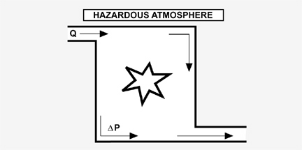
Figure 2. Schematic of a pressurized enclosure
The internal overpressure remains constant with or without a continuous flow of the protective gas. The enclosure must have a certain degree of tightness; however, there are no particular mechanical requirements because the pressure supported is not very high.
To avoid pressure loss, the protective gas supply must be able to compensate, during operation, for enclosure leakage and access by personnel where allowed (the use of two interlocked doors is the classical solution).
Because it is possible for the dangerous mixture to remain inside the enclosure after the pressurization system has been turned off, it is necessary to expel the remaining gas by circulating a certain quantity of protective gas before restarting the electrical equipment.
The classification of the electrical apparatus must be based on the maximum external surface temperature of the enclosure, or the maximum surface temperature of the internal circuits that are protected with another protection method and that remain powered even when the protective gas supply is interrupted.
The purging, or pressurization, technique is not dependent upon the classification of the gas. Rather, the enclosure is maintained at a pressure higher than the dangerous external atmosphere, preventing the flammable mixture from coming in contact with the electrical components and hot surfaces inside.
In the United States the term "pressurization" is limited to Class II applications. This is the technique of supplying an enclosure with clean air or an inert gas, with or without continuous flow, at sufficient pressure to prevent the entrance of combustible dusts. Internationally, the term "pressurization" refers to a purging technique for Zones I and 2.
The North American practice of the purging protection method is based on the reduction of the classification inside the enclosure to a lower level. The following three types of protection (X, Y and Z) are identified in relation to the hazardous-location classification and the nature of the apparatus.
- Type X: reduces the inside of the enclosure from Division 1 to a non hazardous state that requires an automatic shutdown of the system in case of pressure loss.
- Type Y: reduces the inside of the enclosure from Division 1 to Division 2.
- Type Z: reduces the inside of the enclosure from Division 2 to a non hazardous state, requiring alarm signals only.
The European standard regarding this protection method, CENELEC EN 50.016, requires that particular safety systems function regardless of internal protective gas loss due to leakages, shutdowns, compressor breakdowns or operator errors.
Pressurization is allowed as a method of protection in Zones 1 and 2. In the case of pressure loss, an automatic shutdown of the power supply can occur even with a slight delay for Zone 1, while a visual or audible signal is sufficient for Zone 2.
The European and the American practices are quite similar. The safety devices (pressure sensors, flowmeters, delay relays, etc.) needed to activate the alarm or the shutdown of the power supply must be either explosion-proof or intrinsically safe because, as a general rule, they are in contact with the dangerous mixture both on the outside of the enclosure and on the inside during the expulsion phase or during pressure loss.
Sometimes the internal overpressure protection method is the only possible solution, i.e., when no other method of protection is applicable. For example, in the case of large electrical apparatus or control panels where the dimensions and high-energy levels make it impractical to use an explosion-proof enclosure or the application of the energy limitation method, the internal overpressure protection method is often the only answer.
The use of pressurization is limited to the protection of apparatus that do not contain the source of an inflammable mixture. For this type of apparatus, such as gas analyzers, the continuous-dilution technique must be used. This technique always keeps the protective gas—air or inert gas—in a quantity such that the flammable mixture concentration never exceeds 25% of the lower explosive limit of the gas present.
The safety devices for the continuous-dilution technique are similar to the ones used for pressurization, except that the alarm or the power supply is based on the quantity of the protective gas flow instead of the internal pressure.
The continuous-dilution technique is regulated by national standards in Europe, the United States and Canada; however, it is not addressed in the CENELEC standard.
ENCAPSULATION
The encapsulation protection method is based on the segregation of those electrical parts that can cause the ignition of a dangerous mixture in the presence of sparks or heating, by potting in resin that is resistant to the specific ambient conditions. (refer to Figure 3).
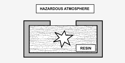
Figure 3. Schematic of encapsulation protection method
This protection method is not recognized by all the standards.
Encapsulation ensures a good mechanical protection and is very effective in preventing contact with an explosive mixture. Generally, it is used to protect electrical circuits that do not contain moving parts, unless these parts, (e.g. reed relays) are already inside an enclosure that prevents the resin from entering. This technique is often used as a complement to other protection methods.
Intrinsic safety requires that some electrical components must have adequate mechanical protection in order to prevent an accidental short circuit. In this situation, potting with resin is very efficient. Zener barriers, for example, are usually potted in resin as required by the standards.
OIL-IMMERSION PROTECTION METHOD
According to this protection method, all electrical parts are submersed in either nonflammable or low-flammability oil, which prevents the external atmosphere from contacting the electrical components. The oil often serves also as a coolant (refer to UL 698 or IEC 79-6).
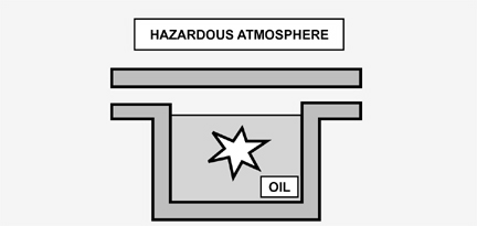
Figure 4. Schematic of oil-immersion protection method
The most common application is for static electrical equipment, such as transformers, or where there are moving parts, such as transmitters. This method is not suitable for process instrumentation or for apparatus that require frequent maintenance or inspections.
POWDER-FILLING PROTECTION METHOD
This protection method is similar to the oil-immersion method of protection, except that the segregation is accomplished by filling the enclosure with powdered material so that an arc generated inside the enclosure will not result in the ignition of the dangerous atmosphere (refer to Figure 5).
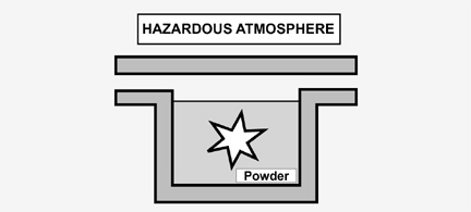
Figure 5. Schematic of the powder-filling protection method
The filling must be made in such a way as to prevent empty spaces in the mass. The filling material that is generally used is quartz powder, and its granularity must comply with the standard.
SEALING, LIMITED-BREATHING AND DUST-PROOFING PROTECTION METHODS
Based on the segregation concept, these techniques do not have a specific standard, but they are often used as a complement to other protection methods.
The principle purpose of these techniques is to ensure that an enclosure containing electrical parts or hot surfaces is sufficiently tight to limit the entry of gas or flammable vapors so that the accumulated gas or vapor is for a period longer than the one relative to the presumed presence of the dangerous mixture in the external atmosphere.
Therefore, the enclosure must have a certain degree of protection (protection index [IP] against the input of solid material and water) that is not inferior to the one required for the type of expected usage.
It is important not to confuse a tight enclosure with an explosion-proof one. Generally, an explosion-proof enclosure, due to its nature, is also tight, but the opposite is not true; a tight enclosure, even with a very high protection index, is not explosion-proof.
INCREASED SAFETY PROTECTION METHOD
This protection method is based on the prevention concept.
Measures must be applied to the electrical apparatus such as to prevent, with an elevated safety coefficient, the possibility of having excessive temperature or the generation of arcs or sparks inside and outside the apparatus during normal functioning (refer to Figure 6).
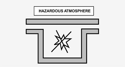
Figure 6. Schematic of increased safety protection method
The increased safety method of protection was developed in Germany and is recognized in Europe by the CENELEC EN 50.019 standard. This method is not adopted in the United States or Canada.
The increased safety technique is suitable for Zones 1 and 2. This technique can be used for the protection of terminals, electrical connections, lamp sockets and squirrel gauge motors, and is often used in combination with other methods of protection.
According to the standard, the prescribed means of construction must be made in such a way as to obtain an elevated safety coefficient during normal functioning. In the case of eventual allowed overloading, construction must comply to very specific standards regarding connections, wiring, components, distances in air and on surfaces, isolators, mechanical impact and vibration resistance, degree of protection of the enclosure, etc. Particular attention must be given to those parts of the apparatus that could be sensitive to temperature changes, such as motor windings.
INTRINSIC SAFETY PROTECTION METHOD
Intrinsic safety is the protection method most representative of the prevention concept and is based on the principle of the limitation of the energy stored in the electrical circuits.
An intrinsically safe circuit is virtually incapable of generating arcs, sparks or thermal effects that are able to ignite an explosion of a dangerous mixture, both during normal operation and during specific fault conditions (refer to Figure 7).
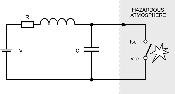
Figure 7. Schematic of an intrinsically safe circuit
In the United States and Canada, intrinsically safe systems are allowed two independent faults. This means that two different and unrelated failures can occur, such as a short circuit of the field wiring and a component failure, and the system will still be safe.
According to the CENELEC EN 50.020 standard, two categories of intrinsic safety—Ex "ia" and Ex "ib"—are specified, defining the number of faults allowed for specific classifications and the safety coefficients to be applied during the design phase.
Category "ia" allows up to two independent faults and can be used for a Zone 0 application, while category "ib" allows only one fault and can be used for a Zone 1 application.
The intrinsic safety method of protection is the only method that protects the apparatus and its relative wiring in hazardous locations, including the breaking, short-circuiting or accidental grounding of the connecting cable. Installation is greatly simplified because there are no requirements for metal-clad cables, conduits or special devices. Also, maintenance and check procedures can be carried out by competent personnel, even when the circuit is being powered and the plant is functioning.
The intrinsic safety method of protection is intended for process instrumentation applications where the low power required is compatible with the energy- imitation concept. In general, when the hazardous location apparatus requires less than 30 V and 100 mA during fault conditions, intrinsic safety is the most effective, reliable and economical protection method. (For installation information, refer to ISA RP12.6 and NEC Article 504).
For those applications in the presence of gas or vapors belonging to Groups C and D, voltages and current values larger than the value indicated above can be used.
NON INCENDIVE, OR SIMPLIFIED PROTECTION METHOD
The concept of non incendive circuitry is defined by the National Electrical Code, NFPA 70, as "a circuit in which any arc or thermal effect produced, under intended operating conditions of the equipment, is not capable, under specified test conditions, of igniting the flammable gas, vapor or dust-air mixture."
To better understand the two key phrases—"under intended operating conditions" and "under specified test conditions"—refer to ANSI/ISA-S12.12. Electrical Equipment for Use in Class I, Division 2 Hazardous (Classified) Locations.
This method, when applied to electrical apparatus, makes the apparatus incapable of igniting a surrounding dangerous mixture during normal functioning.
Non incendive and intrinsic safety protection methods are both based on the prevention concept. However, for the non incendive approach, the device or circuit is not evaluated for safety under fault conditions. As a result, energy surges, equipment faults and static electricity are not addressed. For this reason, non incendive devices are not approved for Division 1.
The determination of whether a circuit or system is non incendive is left to the user. Most end-users are reluctant to install equipment classified as non incendive in Division 2 locations without further protection. The ambiguity of the specification leaves enough doubt that the system will be safe under both normal and fault conditions that the decision is often made to employ intrinsic safety as the protection method.
The prescribed methods of construction are similar to the ones required by the increased safety protection method—specifically, relating to components, enclosures, connection elements, surface temperatures, distances, etc.
This technique, due to its nature, is allowed only in Division 2 where the probability of danger is very low. This appears to be a limiting factor, but it is important to keep in mind that approximately 80% of the hazardous locations in a plant are classified as Division 2. An excellent example in the use of the non incendive, or simplified protection method, is as follows:
A multiplexer located in Division 2 handles signals from Division 1 and transmits them to the control room, which is classified as a non hazardous location. In this application, the combination of the intrinsic safety and the non incendive (simplified) methods of protection represent the most rational, effective and economical solution to the problem.
SPECIAL PROTECTION METHOD
Originating in Germany and standardized in the United Kingdom, this protection method is not covered by any CENELEC or IEC standard and is not recognized in North America. It was developed to allow certification of apparatus that is not developed according to any of the existing protection methods, but can be considered safe for a specific hazardous location. This location must undergo appropriate tests or a detailed analysis of the design.
The use of the special protection method is generally applied to Zone l; however, Zone 0 certification is not excluded.
MIXED PROTECTION METHODS
In the process instrumentation field, the use of several protection methods applied to the same apparatus is a common practice. For example, circuits with intrinsically safe inputs can be mounted in pressurized or explosion-proof enclosures.
Generally, this mixed system does not present installation difficulty if each of the protection methods is appropriately used and is in compliance with the respective standards.
SUMMARY OF PROTECTION METHODS
This paper has briefly presented the protection methods against fire and explosion. The concepts upon which these methods are based were introduced, and the general methods of construction and application were discussed.
The purpose of this paper is not to exhaust the subject, but rather to offer an overview of the applicable protection methods for the electrical instrumentation used in that part of the plant classified as hazardous.
The following table presents a summary of the protection methods against explosion, stating the functioning principles from both the North American and European practices.
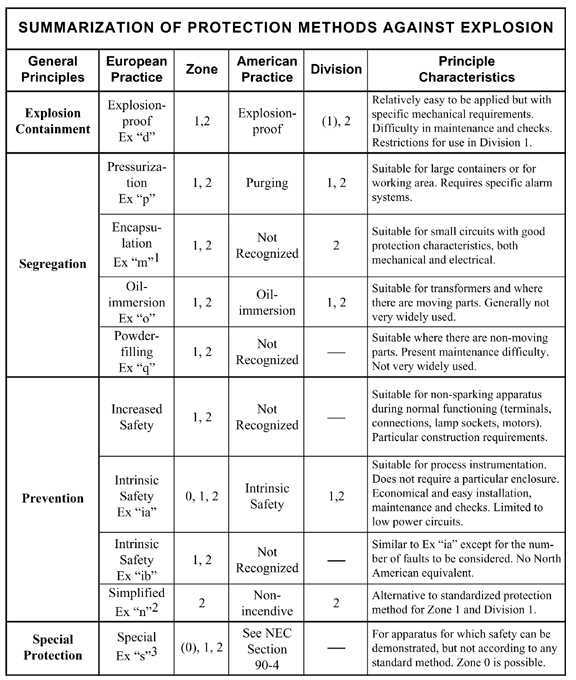
Table 3.1
1 This protection method is currently in a state of revision due to the standardization of CENELEC.
2 In reality, the principle of protection method "n" includes a combination of protection methods, including a simplification of intrinsic safety that is defined as "energy limitation."
3 This protection method is standardized only in Great Britain and Germany.
COMPARISONS BETWEEN THE MOST WIDELY USED PROTECTION METHODS
In the process instrumentation field, the most widely used methods of protection to reduce fire and/or explosion dangers are intrinsic safety, the use of explosion-proof enclosures and purging, or pressurization.
A summary comparison of these methods is shown in the following table (+, - and = respectively denote better, less or equal in relation to the explosion-proof method of protection).
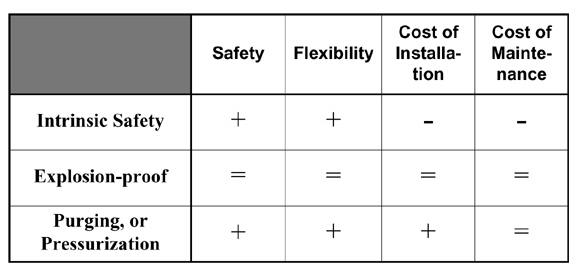
Table 2. Comparison of the most widely used protection methods
The explosion-proof protection method is the most widely known and has been used in applications for the longest period of time. However, it is generally agreed that the intrinsic safety protection method is safer, more flexible and costs less to install and maintain.
Safety
The analysis of the probability of ignition of a dangerous mixture could make one believe that a particular protection method has a degree of protection greater or lower than the others.
The explosion-containment method, for example, has a much higher risk probability than does intrinsic safety (10-7 vs. 10-17). However, from a statistical point of view after over 50 years of use, there has been no report of the occurrence of an accident due to the use of an explosion-proof enclosure. Therefore, the consideration of an increased safety factor of one protection method over another is incorrect. If a system is properly designed and installed, there is no practical difference where the safety factor is concerned.
The safety factor considers only the human factor as the principle cause of a dangerous event or fault. From this point of view, the argument for the use of intrinsic safety as a protection method above the other methods is that it presents a minor dependence on human error.
The use of pressurization and explosion-proof enclosures requires more maintenance; therefore, these methods are more subject to incorrect maintenance that could endanger the safety of the system.
Flexibility
Purging, or pressurization, is more flexible than the explosion-proof method because purging is not related to the type of dangerous atmosphere present and, despite its complexity, can be used where no other application is suitable.
Intrinsic safety, even if a relationship exists to the type of atmosphere present, is the only protection method that does not require specific wiring methods; therefore, the configuration and installation of the system is simplified, even for extremely dangerous hazardous locations classified as Division 1 or Zone 0.
Installation Costs
The standard relative to intrinsic safety allows the installation of apparatus in a similar way to the practice used for standard apparatus. This factor alone lowers the cost of installation.
Explosion-proof and pressurized enclosures require special devices, such as metal-clad cables, conduits, cable clamps, etc. Purging, or pressurization also requires a pipeline for the protective gas. These are the principle reasons for the higher installation cost when these protection methods are used rather than intrinsic safety.
Maintenance Costs
Relative to maintenance costs, intrinsic safety is the most advantageous because this method allows live maintenance with no need for plant shutdown. Intrinsic safety is also more reliable due to the use of infallible and derated components as prescribed by the standards.
Explosion-proof enclosures require that particular attention be given to the integrity of the coupling joints and cable entrance, which adds to the cost of maintenance over a period of time.
For pressurized enclosures, there is an added cost for the maintenance of the protective gas supply system and its relative piping.
Conclusion
From the comparison of the three most widely used protection methods, it is evident that intrinsic safety, where applicable, is preferred for safety and reliability reasons. Intrinsic safety is also the most economical for installation and maintenance.
The use of intrinsic safety provides the best mix of an affordable system and safety requirements.
This article was written and provided by Pepperl+Fuchs.
Registered
4
Average
daily search
70%
Effective
search
238
Registered
companies
You are using BETA version.
Send feedback