

6371
EXPLOSION PROTECTION - TECHNICAL PRINCIPLES
04/25/2017
As Ex areas are not equally hazardous, equipment is subject to different requirements. Techical principles chapter provides more information about zone classification, equipment categories, the equipment protection level (EPL), different equipment groups, ignition temperature and temperature classes. You can find out about the various protection types and familiarise yourself with marking principles.
ZONE CLASSIFICATION
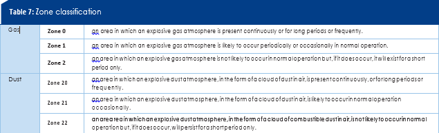
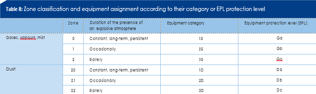
Hazardous areas are classified into zones to facilitate the selec- tion of appropriate electrical apparatus as well as the design of suitable electrical installations. Zone classification reflects the likelihood of the occurrence of an explosive atmosphere (see Table 7). Information and stipulations on zone classification can be found in IEC 60079-10-1 for gas explosion hazardous areas or in IEC 60079-10-2 for areas with combustible dust. There are also industry codes and national standards providing guidance or examples for area classification (see Annex K of IEC 60079-10-1).The maximum risk potential has to be taken into account when classifying the hazardous areas into zones and determining the necessary protective measures. If there is no expert available in the company to assess the risk of explosion and determine the necessary measures, the advice of a competent authority should be sought. The equipment used in the defined hazardous zone must meet the requirements of the respectively assigned equipment category or equipment protection level. An overview of the zone classification and assignment of equipment according to their category is illustrated in Table 8.
EQUIPMENT CATEGORIES AND EQUIPMENT PROTECTION LEVEL (EPL)
Different safety requirements are demanded of the equipment used depending on the likelihood of the occurrence of an explo- sive atmosphere. The equipment protection level is matched to the hazard potential in the different zones. In Europe explosion-protected equipment is classified into cate- gories by EU Directive 2014/34 (ATEX). At international level the equipment protection level (EPL) was introduced by IEC 60079 in 2007. Equipment should be designed with explosion protection meas- ures of varying degrees according to its category or equipment protection level.
Equipment categories
Three categories are envisaged for equipment in hazardous areas – with the exception of firedamp-endangered mining works:
Category 1: Equipment in this category is characterised by a very high degree of safety. Even in the rare event of equipment faults they must be safe and thus afford explosion protection
so that:
- upon the failure of one device protective measure, at least a second separate protective measure will guarantee the necessary
- upon the occurrence of two different faults the necessary safety is
Category 2: Equipment and systems offer a high degree of safety.
The device explosion protection measures in this category are ensured in the case of frequent equipment faults or fault conditions (which can be typically expected).
Category 3: Equipment in this category affords the necessary degree of safety in normal operation.
The additional letter G or D indicates the use of the equipment in gas explosion hazardous areas (G) or areas with combustible dust (D).
Two categories are envisaged for equipment used in firedamp- endangered mining works:
Category M1: Equipment in this category is characterised by a very high degree of safety. Even in the rare case of equipment faults they must be able to continue operating in the existing explosive atmosphere and thus display explosion protection measures so that:
- upon the failure of one device protective measure, at least a second separate protective measure will guarantee the necessary
- upon the occurrence of two different faults the necessary safety is
Category M2: Category M2 equipment and systems offer a high degree of safety. Upon the occurrence of an explosive atmos- phere it must be possible to switch off the equipment. The device explosion protection measures in this category afford the necessary degree of safety in normal operation – even in adverse operating conditions and in particular when exposed to rough handling and fluctuating environmental influences.
Equipment protection level (EPL):
Pursuant to IEC 60079-0 equipment for hazardous areas is classified into three protection levels.
EPL Ga or Da: Equipment with a very high protection level for use in hazardous areas. In normal operation this equipment represents no risk of ignition in the event of predictable or rare faults/malfunctions.
EPL Gb or Db: Equipment with a high protection level for use in hazardous areas which represents no risk of ignition in normal operation or in the event of predictable faults/malfunctions.EPL Gc or Dc: Equipment with an advanced protection level for use in hazardous areas. There is no risk of ignition during normal operation. The equipment has additional protective measures that ensure no risk of ignition in the event of typically predictable equipment faults.
The letters G and D denote whether the equipment and systems are suitable for gas explosion hazardous areas (G) or areas with combustible dust (D). Two protection levels are defined for firedamp-endangered mining works.
EPL Ma: Equipment with a very high protection level that affords the necessary degree of safety. The equipment represents no risk of ignition in normal operation or in the event of predictable or rare faults/malfunctions – even if it is still in operation during a gas leak.
EPL Mb: Equipment with a high protection level that affords the necessary degree of safety. The equipment represents no risk of ignition in normal operation in the period between the occurrence of the gas leak and switching off the equipment.
Table 8 illustrates the application range for equipment in a spe- cific category or with a specific protection level in the respective danger zones.
EQUIPMENT GROUPS
Classification pursuant to European Directive 2014/34/EU (ATEX)
The explosion-protected equipment is classified into two groups.
Equipment group I
Equipment intended for use in underground mining works and surface mining works that may be exposed to the hazard of firedamp and/or combustible dust.
Equipment group II
Equipment intended for use in other areas that may be exposed to an explosive atmosphere.
Electrical equipment for mining works in which in addition to firedamp, gases other than methane may occur, must adhere not only to Group I provisions, but also to the relevant provisions of Group II. Group II equipment is further classified according to application area into equipment for areas exposed to gases, vapours and mist and equipment exposed to dust.
Classification pursuant to IEC 60079
Two groups were formerly defined for explosion-protected equipment.
Group I
Equipment for firedamp-endangered mining works.
Group II
Equipment for hazardous areas – apart from mining.
Upon publication of IEC 60079-0 in 2007 Group III was introduced for dust explosion hazardous areas. Group II is reserved for equipment in gas explosion hazardous areas.
Group II
Equipment for gas explosion hazardous areas – apart from mining.
Group III
Equipment for dust explosion hazardous areas – apart from mining.
Electrical equipment in Group II (gas) is classified according to the characteristics of the explosive atmosphere (for which it is intended) into Groups IIA, IIB and IIC (Table 9). This assign- ment concerns the flameproof enclosure and intrinsic safety protection types. In the case of flameproof enclosures, it is based on the maximum experimental safe gap (MESG), which is a measure for the discharge behaviour of a hot flame through a narrow gap. The minimum ignition current (MIC) – a variable for the minimum ignition energy of emergent gases and vapours – is definitive for intrinsic safety. Equipment in dust explosion hazardous areas (Group III) is classified according to dust type into Group IIIA (combustible lint), IIIB (non-conductive dust) and IIIC (conductive dust). The latter two groups differ by specific electrical resistance, which for dusts in Group IIIC lies at a value less than or equal to 10³ Ùm.
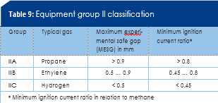
The substances and thus the hazardous areas in which they occur are therefore classified into groups. The equipment deployed must be designed for the requirements of the groups, which range in ascending order from IIA to IIC and IIIA to IIIC. Equipment that complies with IIC criteria may also be used in IIB and IIA areas. Group IIB equipment may also be used in IIA areas. IIA equipment may only be used in IIA areas. This applies likewise for Group IIIA, IIIB and IIIC equipment.
IGNITION TEMPERATURE AND TEMPERATURE CLASSES
The ignition temperature of an explosive gas atmosphere or dust cloud is the lowest temperature of a heated surface at which a mixture of air and combustible substances in the form of gas, vapour or dust may ignite in the specified conditions.
Combustible gases
Combustible gases and vapours are classified into temperature classes according to their flammability. The maximum surface temperature of electrical equipment must always be lower than the ignition temperature of the gas or vapour and air mixture in which it is used. Of course, equipment classified in a higher temperature class (e.g. T5) may also be used for applications in which a lower temperature class is required (e.g. T2 or T3). North America has a system with further classification into temperature subclasses.
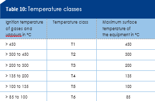
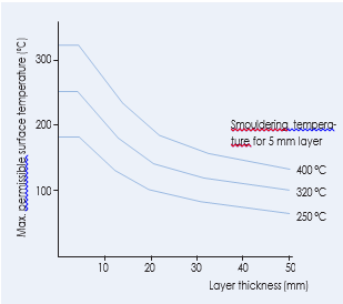
Figure 4: Establishment of the max. surface temperature for dust layers of 5 mm to 50 mm
Combustible dusts
Combustible dusts are not classified into temperature classes. The minimum ignition temperature of the dust cloud is compared with the maximum surface temperature of the equipment, taking a safety factor into account. The maximum equipment surface temperature must not exceed two thirds of the dust cloud ignition temperature. Since dust can also settle on equipment, the ignition temperature of the dust layer (smouldering temperature) must also be considered. The smouldering temperature is the lowest temperature of a hot surface on which a dust layer of 5 mm can ignite. Adjustment based on the maximum equipment surface tempera- ture is performed with a safety factor of 75 K. As heat insulation increases with thicker layers the maximum permissible equip- ment surface temperature should be reduced accordingly. This is established according to the diagram (Fig. 4) in IEC 60079-14. If the layer is thicker than 50 mm, the smouldering temperature must be determined by laboratory tests. This also applies to layers thicker than 5 mm when the smouldering temperature is lower than 250 °C. Laboratory tests are also required when equipment is completely covered with combustible dust. Critical equipment surfaces may not be hotter than the lower of the two permissible surface temperatures with reference to the dust cloud and layer.
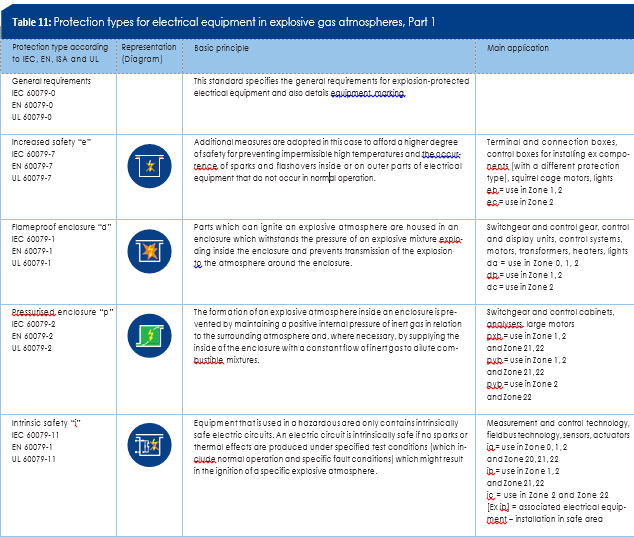
PROTECTION TYPES
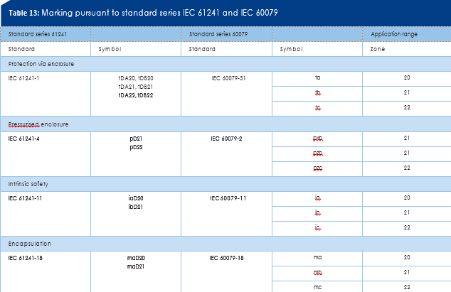
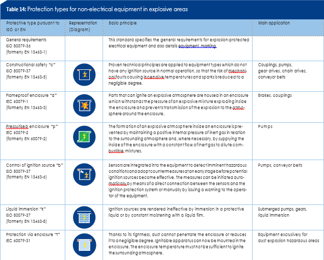
Explosion-protected equipment is predominantly used in loca- tions with a threat of explosion. Explosion-protected electrical equipment for hazardous areas may be designed as per stand- ard series IEC 60079 building provisions in various protection types. Protection types for non-electrical equipment are speci- fied in the ISO 80079 standard series and formerly in EN 13463 in Europe. The protection type used by a manufacturer for equipment main- ly depends on its nature and function. Some protection types are available in different protection levels. They correspond to the equipment categories in Directive 2014/34/EU or the equipment protection level (EPL) in IEC 60079-0. In terms of intrinsic safety, an Ex ia version is available, although it is classified as Category 1 or EPL Ga. It may be installed in Zone 0. The Ex ib version corre- sponds to Category 2 or EPL Gb. It is suitable for Zone 1. Ex ic can be used as Category 2 or EPL Gc in Zone 2. In safety terms, all standardised protection types in a category or equipment protection level may be deemed equivalent. Tables 11 and 12 provide an overview of the standardised protection types and describe the basic principle and customary use cases. The pro- tection type symbols are simplified (Table 13) by integrating the protection types for dust explosion hazardous areas into the standard series 60079.
APPLICATION OF PROTECTION TYPE INTRINSIC SAFETY “i”
The intrinsic safety protection type is based on the principle of current and voltage limiting in an electric circuit. The electric circuit energy (which may be capable of causing an explosive atmosphere) is limited to the extent that neither sparks nor impermissible surface heating of electrical components can take place in the surrounding explosive atmosphere. This protection type is particularly common in measurement and control technology in which no high currents, voltage and capacities are required.
Intrinsically safe electrical circuit
An electric circuit in which neither a spark nor the effect of heat can cause a certain explosive atmosphere to ignite.
Intrinsically safe electrical equipment
Electrical equipment in which all circuits are intrinsically safe.
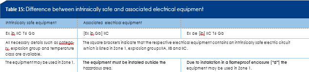
Associated electrical equipment
Electrical equipment that contains both intrinsically safe and non-intrinsically safe electric circuits. It is designed such that the non-intrinsically safe electric circuits cannot compromise the intrinsically safe ones (Table 15).
An essential aspect of the protection type “intrinsic safety” is the matter of reliability in respect of observance of voltage and current limit values, even in the event of specific faults.
Intrinsically safe electrical equipment and parts of associated equipment are classified according to this reliability into the different protection levels ia, ib and ic. These protection levels are matched to the various zones. Intrinsic safety ia is thus suitable for use in Zone 0, ib for use in Zone 1 and ic for Zone 2.
A distinction is also drawn between singe fault safety and double fault safety:
- Single fault safety: Upon the failure of one safety-relevant component a second component must assume its task (protection level ib: one redundant component).
- Double fault safety: Upon the failure of two safety-relevant components a third component must assume their tasks (protection level ia: two redundant components).
An important safety measure for intrinsically safe circuits is the safe isolation of all intrinsically safe from all non-intrinsically safe electric circuits. Excepting safety barriers, safe electric isolation is always required. Galvanic separation is generally recommended for Zone 0. Zener diodes for limiting voltage and other semiconductor components are regarded as fallible and must be safeguarded by redundant components. Sheet or wire- wound resistors for current limiting are regarded as infallible (displaying high resistivity in the event of a fault). A single-com- ponent version is sufficient in this case.
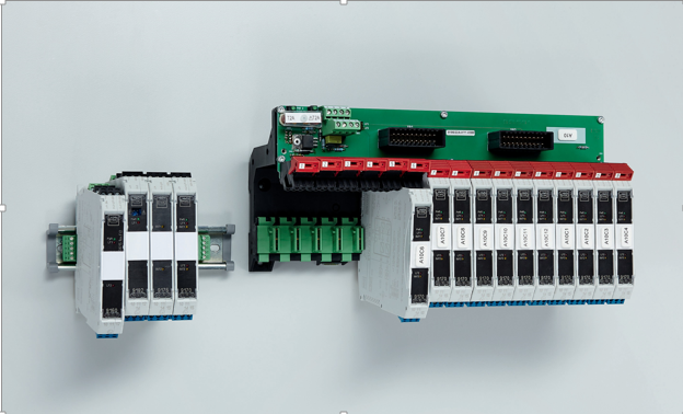
Figure 5: Isolators with IS pac galvanic separation
Interconnecting individual pieces of equipment in an intrinsic- ally safe circuit is permissible subject to the planner observing specific requirements. If associated equipment is interconnected to intrinsically safe equipment, when installing the circuit it should be ensured that the safety characteristic values of the associated and intrinsically safe equipment are matched. (See IEC 60079-14 and IEC 60079-25 for more details on interconnec- tion.) The operator must hold proof of intrinsic safety for all intrinsically safe circuits. If available, a system certificate is deemed as proof.
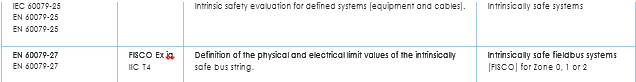
Intrinsically safe fieldbus to FISCO (Fieldbus Intrinsically Safe Concept)
In the case of Manchester-coded bus-fed systems designed in accordance with IEC 61158-2 (“physical layer standard” for fieldbus installations) several field devices are interconnected on a two-wire line and powered via a fieldbus feed unit. This complex interconnection of several devices would result in considerable restrictions in respect of the number of users and line lengths based on a traditional entity concept. The neces- sary proof of intrinsic safety would be substantial and highly complex. In the mid-1990s PTB therefore developed a simplified concept based on extensive studies and analyses. By applying real parameters more users and more sizeable line lengths are possible, thus greatly simplifying the proving of intrinsic safety. Prerequisite to using this model called FISCO is appropriate certification according to FISCO for all members in a FISCO fieldbus system. FISCO was initially standardised in EN 60079-27, however was transferred into EN 60079-11 in 2008 and EN 60079-25 in 2011. Nowadays end-to-end FISCO fieldbuses are no longer generally installed, as despite simplification only a limited number of users can be connected to a bus. In the more common high power trunk concept the number of users is no longer limited by the use of ex i fieldbus couplers (a sort of fieldbus isolator). However activation of the fieldbus devices and simplified proof of intrinsic safety on these Ex i couplers continues to be performed as per FISCO.
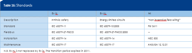
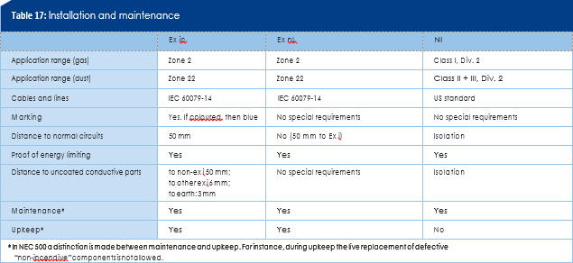
Zone 2 and Division 2: Intrinsic safety ic – energy- limited circuits nL – non-incendive NI
In the USA the principle of energy limiting is addressed variously depending on the application area. Equipment requirements for Class I, Zone 2 correspond most closely to IEC requirements. In- trinsic safety type ic has replaced the energy-limited circuit type nL – as also envisaged in the IEC standards. For Class I, Division 2 energy limiting is implemented in the shape of “non-incendive field wiring (NI)” circuits. The difference between the various methods is illustrated in tables 16 and 17.
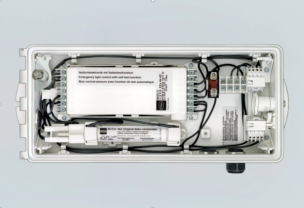
Figure 6: Combination of protection types for an emergency luminaire
APPLICATION AND COMBINATION OF PRO- TECTION TYPES FLAMEPROOF ENCLOSURE “d” AND INCREASED SAFETY “e”
The most important protection type for switchgears is the flame- proof enclosure – usually combined with increased safety. The protection type increased safety is based on measures that afford a higher degree of safety to avoid the occurrence of ignition sources. However, switchgears produce sources of ignition, and this protection type alone is not sufficient to ensure explosion protection. In conjunction with increased safety, flameproof enclosure as protection type also plays an important role for switchgears. Modern, explosion-protected luminaires also use a combination of several types of protection to achieve the best results with regard to safety, function and economy (Fig. 6).
APPLICATION OF THE PROTECTION TYPE CONSTRUCTIONAL SAFETY “c”
Non-electrical equipment is frequently designed in the construc- tional safety protection type. The risk of faults that may cause ignition sources on equipment is minimised by constructional measures in this type of protection. Constructional measures can be used for instance to avoid hot surfaces or mechanically generated sparks on moving parts. The measures depend mainly on the equipment type and may vary significantly. In this case, potential material pairing, dimensioning, tolerances and lubri- cants on moving parts play a role. Even maintenance intervals and life cycle monitoring may be of vital importance. The manu- facturer defines the designated use in the operating instruc- tions, also specifying the ambient and operating conditions and permissible operating parameters. The operator must adhere to the specifications in the operating instructions.
MARKING
Worldwide (IEC)
Marking of electrical equipment is defined in IEC 60079-0. In addition to the name of the manufacturer or its trademark, the type designation, serial number and inspection authority with certificate number, a special code is required that describes the use of the equipment:
- The Ex
- The symbol for every protection type (In the case of associated equipment for installation in dangerous areas, the symbols for the type of protection must be specified in square brackets.)
- Group IIA, IIB or IIC for gas explosion hazardous areas or Group IIIA, IIIB or IIIC for dust explosion hazardous
- Temperature class for gas explosion hazardous areas or maximum surface temperature in °C for dust explosion hazardous
- Explosion protection level (EPL ).
Examples:
Ex d e IIC T4 Gb
Ex ta IIIC T120°C Da
The EPL marking can be dispensed with if the protection types clearly show which explosion protection level they achieve. On some protection types this is already denoted by the existing symbols (e.g. ia). On others, the letter a, b or c must be added: d becomes db.
Examples:
Ex db eb IIC T4 Ex ta IIIC T120°C
On associated equipment that may be installed in non-explosive areas, the symbols for the protection type must be specified in square brackets.
Example:
Ex d [ia Ga] IIB T5 Gb or Ex db [ia] IIB T5
The marking of non-electrical equipment is largely identical to that of electrical equipment. However, instead of various symbols for the protection types, the letter “h” is always used.
Europe (ATEX)
In Europe, in addition to marking pursuant to the standard
(see IEC), the requirements of EU Directive 94/9/EC and 2014/34/ EU (ATEX) must also be satisfied. The following data must be specified:
- Manufacturer’s
- CE mark (possibly with code of the named authority).
- The symbol and group (e.g.: II) and Category 1, 2 or 3 and letter G (gases) or D (dust).
Example:
Ex II 2 G
In Europe, instead of “Ex”, “EEx” used to be used when marking in accordance with the standard, e.g. EEx d e IIC T4. A reference was thus made to the European standards (EN 50014 ff.), which at the time differed from the IEC standards. This is no longer necessary due to the current standard status, so that in Europe new equipment is now only marked “Ex”.
Standards for non-electrical equipment were originally issued by CEN in Europe under standard series EN 13463. Marking is similar to that of electrical equipment – with the following exceptions:
- “Ex” is not specified, as the EX mark already refers to explosion protection through
- The equipment protection level is not
- The alternative marking is not used The protection level is to be determined via the category.
These standards were revised at international level and published in 2016. In Europe they were adopted as standard series EN ISO 80079, so marking is now more similar to that of electrical equipment. Exception: “h” is always specified as the symbol for the protection type. The marking for electrical and non-electrical equipment is summarised in the appendix on p. 52 onwards.
North America
In addition to usual data (manufacturer, type, serial no., elec- trical data), explosion protection data should also be included in the equipment marking. Specifications are provided in NEC, CEC and the relevant construction regulations of the inspection authorities.
Electrical equipment approved for Class I, Class II and Class III, Division 1 and Division 2 should be marked so that the following details are included:
- Class(es), Division(s) (optional for Division 1).
- Gas/dust group(s).
- Service temperature or temperature class (optional for T5 and T6).
Example:
Class I Division 1 Groups C D T4 Equipment specified in the USA for zones pursuant to NEC article 505 or 506, or CEC Section 18, should bear the following marking:
- Class (dispensed with in the USA for dust atmospheres and entirely in Canada).
- Zone (dispensed with in Canada).
- Symbol AEx (USA) or Ex (Canada).
- Abbreviation of the protection type(s)
- Group of electrical equipment II or gas group(s) IIA, IIB or
- Temperature class or surface temperature of equipment for dust atmospheres.
- Equipment protection level (EPL).
Example:
Class I, Zone 0, AEx ia IIC T6
Division equipment may be used in zones and vice-versa. However the rules set out in NEC and CEC must be observed.
Original link from: http://www.r-stahl.com
Registered
4
Average
daily search
70%
Effective
search
239
Registered
companies
You are using BETA version.
Send feedback