

6371
Barrier cable gland - what to and how to do?!
02/20/2017
Background - IEC 60079-14:1996 Edition 2 included a selection chart which was taken directly from BS 5345-3:1989. Subsequent editions of IEC 60079-14, up to and including Edition 4 in 2007, retained the selection chart. In Edition 5, which was published in November 2013, the chart was replaced with different criteria. The original selection chart was based on research carried out by ERA in the UK in 1975 based upon concerns that repeated ignitions inside a flameproof enclosure could damage the conductor insulation and inner cable bedding, within or immediately external to the cable gland, to such an extent as to cause a fault which could be a source of ignition to a flammable atmosphere surrounding the enclosure.
The report, in April 1976, made six proposals which related to plastic and elastomeric insulated cables:
- Tape-bedded cables should not be connected into flameproof enclosures, including flameproof terminal boxes, without some form of additional protection (see item d)).
- Extruded-bedded cables should not be connected into direct-entry flameproof enclosures having net free volumes greater than 2 litres without some form of additional protection (see item d)).
- Cables connected into Group IIC flameproof enclosures, including flameproof terminal boxes, should be provided with some form of additional protection (see item d)).
- The additional protection required by proposals a), b) and c) should maintain the flameproof properties of the enclosure, and should reliably prevent penetration of the hot products of combustion into the exposed cable This may be achieved by:
- a special gland; or
- provision of a sealing device, e.g. a stopper box; or
- other equally effective
- Standard industrial cables may be connected using standard industrial glands into flameproof terminal boxes provided they also comply with the requirements for Ex’e’ (increased safety) terminal
- In circumstances where it is known that cables have been connected into direct-entry flameproof enclosures having net free internal volumes greater than 2 litres, consideration should be given to the provision of some form of additional protection. This is particularly urgent where multi-core signal cables are
At the time when the research was carried out, ‘barrier’ glands had not been developed; hence the reference to ‘a special gland’. (Source: National Annex NA (informative) BS EN 60079-14:2014)
So based upon this research, the IEC adopted the following criteria to be adopted and published in 1996 along with the cable gland criteria flowchart that many of us have followed over the past 20 plus years.
“Where a cable is sheathed with thermoplastic, thermosetting, or elastomeric material, is circular, substantially compact, has extruded bedding and fillers, if any, are non hygroscopic, a flameproof cable gland, in compliance with IEC 60079-1, may be utilized, providing this incorporates a
sealing ring and is selected in accordance with Figure 1.”
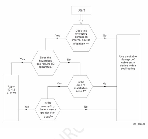
Here you can find the Flowchart
a Internal sources of ignition include sparks or equipment temperatures occuring in normal operation which can cause ignition. An enclosure containing terminals only or an indirect entry enclosure (see 10.4.1) is considered not to constitute an internal source of ignition.
b The term ‘volume’ is defined in IEC 60079-1 (Source: IEC 60079-14:1996 Ed.2 )
So in effect, following this flowchart, the use of a barrier gland as mandated by the standard was limited to applications in which the flameproof enclosure contained a source of ignition (which is a common use for Ex d equipment in housing non-Ex equipment into a hazardous location), was being used in an environment in which it required equipment suitable for IIC gases/vapours regardless of zone or in which the enclosure is being housed into a Zone 1 area in which the enclosure has an internal volume of greater than 2 liters. All other conditions allowed the use of a non-barrier type Ex d cable gland, again assuming the cables being used met the criteria as stated above.
This flowchart and definition remained unchanged until the latest edition of IEC 60079-14:2013 Edition 5 in which the key points for when you are required to use a barrier gland are as followed:
6.2 Selection of cable glands
The cable entry system shall comply with one of the following:
- Cable glands sealed with setting compound (barrier cable glands) in compliance with IEC 60079-1 and certified as equipment;
- Cables and glands meeting all of the following:
- cable glands comply with IEC 60079-1 and are certified as equipment
- cables used comply with 3.2(a)
- the connected cable is at least 3 m in length;
- indirect cable entry using combination of flameproof enclosure with a bushing and increased safety terminal box;
- mineral-insulated metal-sheathed cable with or without plastic outer covering with appropriate flameproof cable gland complying with IEC 60079-1;
- flameproof sealing device (for example a sealing chamber) specified in the equipment documentation or complying with IEC 60079-1 and employing a cable gland appropriate to the cables The sealing device shall incorporate compound or other appropriate seals which permit stopping around individual cores. The sealing device shall be fitted at the point of entry of cables to the equipment.
NOTE 1 The minimum length of cable is to minimize the potential for flame transmission through the cable (see also Annex E);
NOTE 2 If the cable gland and actual cable are certified as a part of the equipment (enclosures) then compliance to 10.6.2 is not necessary. (Source: IEC 60079-14:2013 Ed.5 )
The key points here to note is that under the latest standard, the use of barrier glands vs. non-barrier Ex d glands and equipment has changed.
- Ex d equipment housing arcing/sparking components – Previous version allowed the use of non-barrier glands as long as the enclosure was going into a Zone 2, IIB or IIA environment or in Zone 1 areas in which the enclosure housing arcing/sparking was less than 2 liter volume. The new standard does away with this and states that if the cable is 3 meters or longer, the use of a non-barrier Ex d gland is now acceptable, regardless of area classification and gas
- Ex d equipment housing non-arcing/sparking components – Previous versions allowed the use of non- barrier glands in all applications as again, non-arcing components were used within an Ex d enclosure. The new standard again, now requires a barrier gland for this application where the cable is less than 3
To provide a better understanding of the older and new standard with regards to the use of barrier glands, a few examples are shown below. The following four situations involve a flameproof motor starter and a flameproof motor connected via an cable meeting the requirements of direct entry into a flameproof enclosure:
Picture: Figure 1
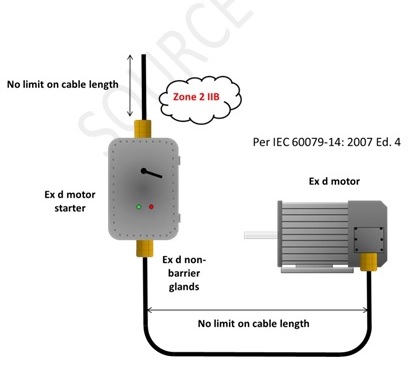
Figure 1: The use of non-barrier glands for direct entry into Ex d enclosures per IEC 60079-14:2007 4th Ed. Note that the use of non-barrier glands are acceptable even into Ex d arcing/sparking enclosures if the environment is Zone 2, IIB.
Picture: Figure 2
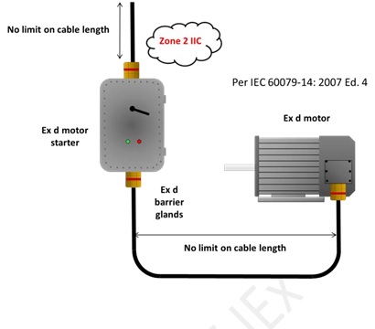
Figure 2: The use of barrier glands for direct entry into Ex d enclosures per IEC 60079-14:2007 4th Ed. Note that the use of barrier glands are required for all Ex d enclosures housing arcing/sparking components in a IIC environment (or also in a Zone 1 IIB if the enclosure volume is greater than 2 liters).
Picture: Figure 3
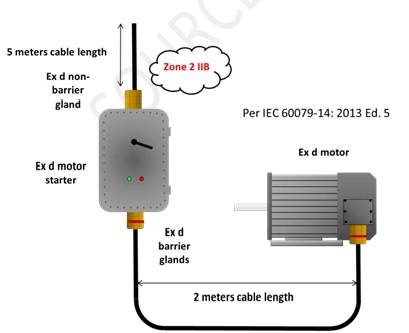
Figure 3: The use of barrier glands and non-barrier glands for direct entry into Ex d enclosures per IEC 60079-14:2013 5th Ed. Note the issue with cable length is now the critical factor of more or less than 3 meters, not the area classification or gas group.
Picture: Figure 4
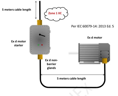
Figure 4: The use of non-barrier glands for direct entry into Ex d enclosures per IEC 60079-14:2013 5th Ed. Note the use of non-barrier glands even in a Zone 1 IIC environment with the connecting cable lengths exceed the 3 meter rule.
As you can see from the diagrams above, some of traditional applications where you may find the need for the use of barrier glands has changed while other specific applications have not. Again, as noted previously, the use of barrier glands with Ex d enclosures with non-arcing components under the older standard was not required, but now depending on the cable length, it certainly can be.
To to summarize, many of these changes have yet to be implemented by clients as they may still be working under the previous standard(s) or as in the case of the UK, not following the new cable gland selection guideline in the latest version of BS EN 60079-14:2014 10.6.2, but instead following the guidelines by the HSE and the information in the back of the BS standard in Annex NA in suggesting the use of the older ‘flowchart’ as a basis for cable gland selection. Whichever standard or guide to follow, it is important to understand the requirements (of both in my opinion) and just as important, make sure that whatever cable gland selected is installed correctly.
As a user, consultant, contractor, inspector or equipment manufacturer, it is critically important now, more than ever, to understand this topic fully in making sure your installation is safe, regardless of which way you proceed.
Link to original article: http://www.sourceiex.com/Catalogs/To%20Barrier%20or%20Not%20to%20Barrier.pdf
Registered
4
Average
daily search
70%
Effective
search
239
Registered
companies
You are using BETA version.
Send feedback